Schematic 3 – In the chamber lift system, one normally utilizes two packers, a standing valve, a perforated pup above the bottom packer, and a differential vent valve just below the top packer, in addition to the Gas Lift Valve necessary to unload and produce the well.While the bottom injection pressure operated valve is closed, the standing valve is open. Fluid fills both the tubing and annular space (chamber) between the two packers. The differential valve is open, and allows gas in the top of the annular part of the chamber to bleed into the tubing as the chamber fills. When the chamber has filled to the point that the liquid level is near the differential valve, the operating gas lift valve opens. A calculated gas volume enters the top of the chamber, closing the bleed valve and standing valve, forcing accumulated liquids to U-tube from the chamber to the tubing. Liquids are produced as a slug to the surface. As the tubing is cleared, the operating gas lift valve closes, the standing valve and bleed valve open, and liquids again refill the chamber. The cycle then repeats.If properly planned, a chamber lift system permits a larger volume of fluid to be produced by intermittent lifts from wells with a high productivity index and low-to medium bottom hole pressure.
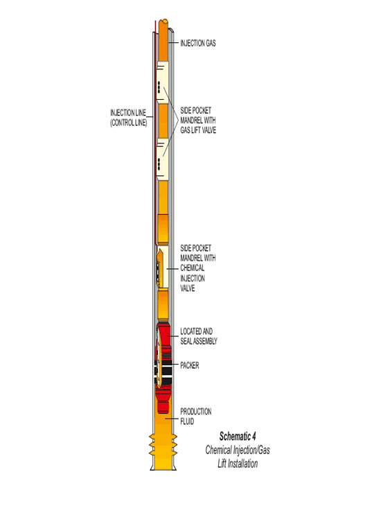
Schematic 4 – In certain cases, Chemical injection is desirable to be coupled with Gas Lift. Side Pocket Mandrels may be run at pre-determined depths for Gas lift valves to be installed. An additional mandrel with a chemical injection valve and injection line may also be run to desired depth on the same tubing string. Tubing / Casing annulus can be used for gas injection and the injection line for chemical injection.