Mounted directly to the Motor Valve, the Electronic Times CycleController with the Two Stage Regulator and Filter Drip is acompact assembly designed to provide the operator with areliable method of obtaining optimum control of a plunger liftinstallation without frequent visual inspection and adjustment ofcycle times. The Electronic Time Cycle controller is, having amicroprocessor based timer that can be programmed to displayname, date or other information. The controller maintains On-Time, OFF-Time & Delay Time.
Each timer is easily set by the operator using the dedicated keys &the display on the front panel. Timer timings can be in hours &minutes or as required so as to achieve maximum accuracy forany operating condition.
The electronic controller features a rugged, watertight enclosure with a clear, see-through front cover that allows the operator to monitor the current cycle being timed without exposing the interior to ambient atmospheric conditions. In addition, the internal electronics are conformably coated for protection against moisture laden air or corrosive gases. The coil in the solenoid valve and current limiting components are totally encapsulated to prevent the possibility of electric arcing in the presence of an explosive atmosphere.
2RBF Two Stage Regulator and Filter Drip is composed of twopressure regulators and a filter-drip pot. The primary highpressureregulator input up to 6000-psi supplies gas and providesa 250-psi inlet supply to the secondary low-pressure regulator.The drip pot contains a stack of felt filters, which in conjunctionwith the sintered metal filter in the high-pressure regulator,provide a dry, clean (particulates less than 4 microns) operatingsupply to the pilot. The drip pot body features an extension forattachment to the motor valve, which permits a compact, unifiedinstallation.
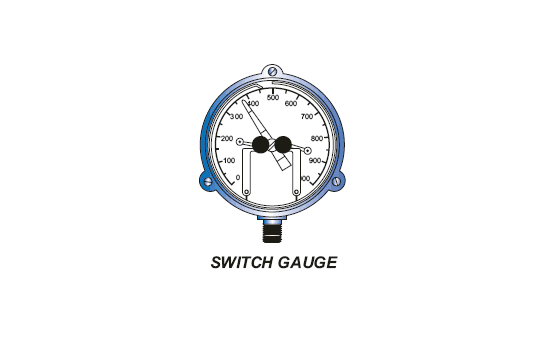
Switch Gauges are conventional pressure gauges withadjustable high and low set points for controlling motor valveoperation in response to well pressure. In operation, the indicatormoves between the set point contact arms, and when the indicatortouches one of the arms, an electric circuit is completed thatgenerates a signal to an electronic timer, which controls theoperation of a motor valve. These contact closure signals areused by the timer to override the programmed time cycles andtypically represent high and low tubing and casing pressure.